













Reverse-Engineering Clamping Force for Large, Thin-Wall LSR Parts: The Diving Mask Sizing Problem
Diving and swim masks, along with other large-format thin-wall silicone products, present a machine selection problem that's genuinely different from sizing equipment for small precision parts. The instinct is often to assume "bigger part means bigger machine, get the largest clamping force available." In practice, the correct approach is closer to reverse engineering: starting from the part's actual projected area and cavity pressure requirements, then working backward to the clamping force the machine actually needs — because both underestimating and overestimating tonnage bring real costs.
- Why Large, Thin-Wall Parts Are a Different Sizing Problem
- The Basic Reverse-Engineering Logic
- Illustrative Example (For Reference Logic Only — Not a Universal Formula)
- Risks of Getting This Wrong in Either Direction
- What to Ask an Equipment Supplier When Sizing for Large Thin-Wall Parts
- The Practical Takeaway
Diving and swim masks, along with other large-format thin-wall silicone products, present a machine selection problem that's genuinely different from sizing equipment for small precision parts. The instinct is often to assume "bigger part means bigger machine, get the largest clamping force available." In practice, the correct approach is closer to reverse engineering: starting from the part's actual projected area and cavity pressure requirements, then working backward to the clamping force the machine actually needs — because both underestimating and overestimating tonnage bring real costs.
Why Large, Thin-Wall Parts Are a Different Sizing Problem
Small precision parts are often sized around cycle time, cavity count, and fine dimensional control. Large thin-wall parts like dive masks are sized primarily around a different constraint: preventing the mold from opening under injection pressure across a large projected area, while still filling a thin cross-section evenly before the material begins to cure.
- Projected area drives clamping force requirements directly. The larger the part's flat projected area (viewed in the direction the mold opens), the greater the total separating force generated during injection at any given internal cavity pressure — this is the core relationship that clamping force sizing is built around.
- Thin walls require higher injection pressure to fill evenly, since thin cross-sections offer more flow resistance per unit length than thicker sections — and higher injection pressure, applied across a large projected area, compounds into a larger total separating force than either factor would suggest on its own.
- Uneven wall thickness across a large, curved part — common in ergonomically shaped products like dive masks — can create localized pressure variation during fill, meaning peak local pressure (not just average pressure) needs to be accounted for when estimating true clamping force needs.
The Basic Reverse-Engineering Logic
While exact calculations depend on part-specific flow simulation, the general logic mold and machine engineers use follows this structure:
Required Clamping Force ≈ Projected Area × Expected Cavity Pressure (with an appropriate safety margin)
The two variables that actually determine machine sizing, then, are:
- Projected area of the part (and the full multi-cavity layout, if more than one cavity is used) — measured in the direction the mold opens, not the part's total surface area.
- Expected peak cavity pressure during fill, which depends on wall thickness, flow length, gate design, and the specific material's viscosity — this is where flow simulation or prior trial data becomes valuable, since assuming a generic pressure figure for "thin-wall parts" in general can significantly under- or overestimate the actual requirement for a specific geometry.
Illustrative Example (For Reference Logic Only — Not a Universal Formula)
The table below illustrates how projected area and required cavity pressure combine to influence clamping force needs — the specific numbers are illustrative to show the relationship, not a substitute for part-specific calculation or simulation.
| Part Type (Illustrative) | Approx. Projected Area | Relative Fill Pressure Needed | Relative Clamping Force Impact |
| Small precision seal | Small | Low–moderate (short flow length) | Low |
| Medium consumer electronics part | Moderate | Moderate | Moderate |
| Large thin-wall dive mask / swim goggle | Large | High (long flow length, thin section) | High — disproportionate to part size alone |
| Large but thicker-wall enclosure | Large | Lower than an equivalently sized thin-wall part | Moderate–high, but lower than a thin-wall equivalent |
The key takeaway from this comparison: two parts with a similar projected area can require meaningfully different clamping force if one has thinner walls or longer flow paths than the other. Projected area alone is not a sufficient sizing input — it has to be paired with a realistic fill pressure estimate for that specific geometry.
Risks of Getting This Wrong in Either Direction
- Undersized clamping force relative to actual injection pressure needs can cause the mold to "breathe" — a slight, repeated opening under pressure — leading to flash, inconsistent wall thickness, and dimensional variation that may not be immediately obvious as a tonnage problem, since it can look similar to other flash-related process issues.
- Oversized clamping force, chosen as a conservative buffer without actual calculation, isn't just a matter of wasted capital cost — larger-tonnage machines also generally have larger footprints, higher energy consumption, and can be less efficient for the actual cycle if platen size and shot capacity don't match the part's real requirements.
What to Ask an Equipment Supplier When Sizing for Large Thin-Wall Parts
- Has flow simulation been done for this specific part geometry to estimate actual peak cavity pressure, rather than relying on a general assumption based on part size alone?
- What projected area and safety margin assumptions were used to arrive at the recommended machine tonnage?
- If multiple cavities are planned, has total projected area across all cavities been factored into the clamping force recommendation?
- Is there trial or reference data from a similarly thin-walled, similarly large part that supports the pressure assumptions being used for sizing?
The Practical Takeaway
For large, thin-wall LSR parts, machine selection isn't a matter of matching part size to machine size intuitively — it's a calculation that starts with projected area and realistic fill pressure for the specific geometry, then works backward to the clamping force actually required. A supplier who walks through this calculation, rather than simply recommending "the next size up" from a standard lineup, is generally offering a more accurate and more cost-appropriate machine recommendation.


You May Also Like
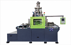
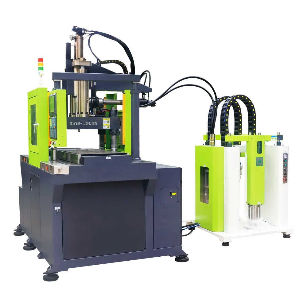
The vertical machine will open and close the mold in the vertical direction. The double slide plate can be installed with one upper mold and two lower molds. It can cooperate with the double station operation to improve the production efficiency, and is more suitable for the production of rubber coated products of silica gel package inserts.
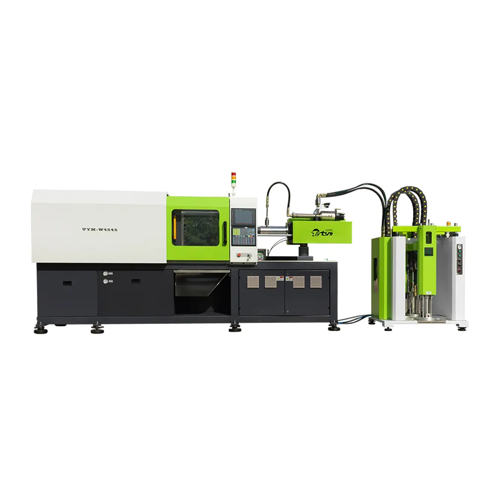
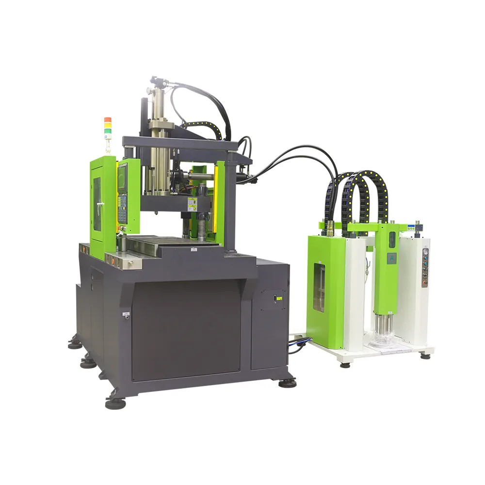
Direct pressure mold opening and closing system.It's more suitable for producing the LSR parts which can be automatically removed from the mold.It can be used for the production of silicone products in multiple industries - automotive wiring harnesses, baby pacifiers, menstrual cups, medical valve plugs.
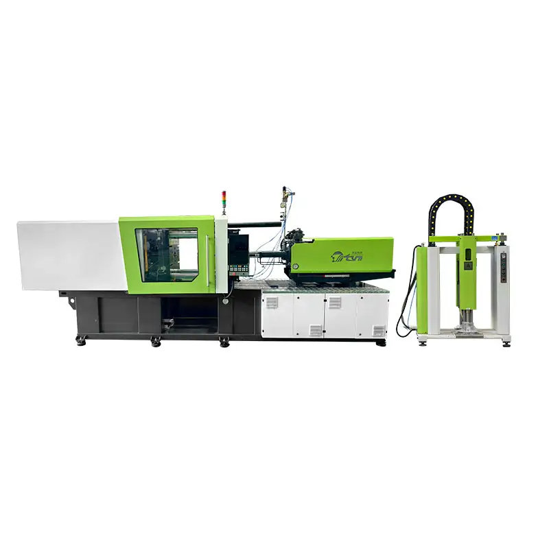
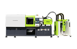
Direct pressure mold opening and closing system.It's more suitable for producing the LSR parts which can be automatically removed from the mold.
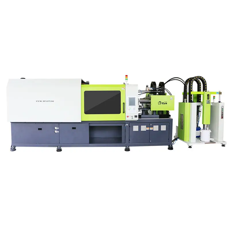
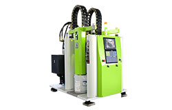
There are two injection units, two separate feed systems and color slurry addition systems. A unified system control panel can be used to achieve two different colors or hardness of liquid silicone. Formed in the machine at the same time, Suitable for the production of double color silicone products or double hardness silicone products.
Inquire About Our Latest Updates
Saw an interesting update or new technology in our news section? Leave us a message below for more detailed information, technical data, or event follow-ups.
Have a project in mind? Talk to our LSR experts and get a tailored turnkey solution.
Email: sales01@gdtym.com
WhatsApp/Phone: +86 18814115468
© 2026 TYM. All Rights Reserved.

Facebook
TikTok
TYM Silicone Machinery