











Vertical Rotary Table vs 3RT LSR Injection Molding Machines
- Start with the production cell, not the machine label
- What a rotary-table architecture changes
- What buyers mean by 3RT
- Compare work content and takt time
- Operator access and ergonomics
- Safety architecture and guarded access
- Tooling strategy and mold ownership
- Automation and peripheral interfaces
- Control logic and traceability
- Maintenance, cleaning, and changeover
- RFQ data that supports a valid comparison
- Factory acceptance testing
- Site acceptance and production handover
- Choose by evidence, not station count
- Relevant configured machine families
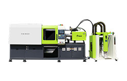
- Vertical Turntable LSR Injection Molding Machine
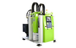
- Vertical 3RT LSR Injection Molding Machine
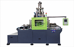
- Vertical LSR Injection Molding Machine
Quick Answer: A vertical rotary-table LSR machine is usually the simpler choice when one accessible lower mold can be loaded or unloaded while another is inside the guarded molding zone. A vertical 3RT machine deserves evaluation when a third defined position separates loading, molding, unloading, inspection, cooling, or automation without creating an idle station. Compare the configured station sequence, tooling count, operator balance, safety logic, robot interfaces, maintenance access, and acceptance evidence. Do not choose by the 3RT label or nominal station count alone.
Start with the production cell, not the machine label
A vertical rotary-table LSR machine and a vertical 3RT LSR machine can both separate molding time from manual or automated handling time, but the label alone does not define the cell. The buyer must map each station to a specific action such as insert loading, molding, cooling, demolding, inspection, or robot transfer. That map should include the number of lower molds, the position of the heated upper mold, and every safety boundary. A useful comparison therefore begins with the part route and operator route rather than a catalog headline.
The planned part family determines whether a simpler rotary arrangement or a multi-station architecture deserves evaluation. Insert-overmolded parts may need generous loading access, positive insert location, and enough protected time for an operator to prepare the next mold. Parts requiring several post-mold actions may benefit from additional station availability, but only when those actions can occur without creating queues. The project team should time each manual and automated task with representative components. A station that has no defined work adds footprint, tooling, controls, and validation without creating useful capacity.
We treat the machine, dosing system, mold, automation interfaces, process setup, acceptance testing, and training as one production unit. This approach prevents a buyer from approving a rotary layout before the mold and handling method are mature. It also exposes responsibility gaps between the machine builder, mold team, robot integrator, and factory engineering group. Every interface should have an owner, an input, an output, and an acceptance method. The final quotation should describe the configured cell rather than rely on a generic model family.
What a rotary-table architecture changes
A rotary table moves one or more lower-mold stations between a loading area and the vertical clamping area. On the currently enabled Vertical Turntable LSR Injection Molding Machine product record, the stated configuration combines vertical mold movement with a rotary table and dual lower molds. The record also describes a servo-driven rotary function and the possibility of robot integration. Those statements establish a product direction, but they do not replace project-specific data for table diameter, allowable tooling mass, indexing logic, guarding, or cycle sequence. Buyers should request the exact configuration proposed for their molds.
The principal operating value comes from separating access from the hazardous molding zone. An operator can prepare an accessible lower mold while the other station is inside the guarded clamp area, subject to the validated safety design. This arrangement can reduce idle time when insert placement or part removal fits within the molding phase. It can also improve ergonomics because the loading point remains in a repeatable location. The benefit disappears when loading consistently takes longer than molding or when downstream inspection blocks the next index.
Rotary movement introduces interfaces that a fixed-platen machine does not have in the same form. Cables, hoses, sensors, ejector connections, temperature circuits, and any vacuum or air lines must tolerate the specified motion and remain protected. The table must arrive at a repeatable, verified position before clamping or injection can proceed. Tooling must clear guards, columns, injection components, and adjacent stations throughout movement. A procurement review should therefore include a motion envelope and an interface drawing, not only a stationary general arrangement.
What buyers mean by 3RT
The term 3RT is commonly used as a model or architecture label, but it should never be treated as a complete technical specification. The enabled TYM product is titled Vertical 3RT LSR Injection Molding Machine, and its current record describes configurable ejection functions and an arrangement intended to support multiple mold activities. The record does not provide a complete station-by-station sequence for every project. Buyers should ask us to mark the exact working position, loading position, unloading position, and any auxiliary position on the proposed drawing. Only that configured drawing can support a reliable comparison.
An additional station can create useful separation between tasks when loading, molding, and removal each need dedicated space or time. It may also create room for a robot, camera, cooling operation, or manual quality check when the process actually requires one. However, three nominal positions do not guarantee three independent productive operations. The clamp arrangement, mold ownership, transfer method, and control interlocks determine what can occur simultaneously. A project team should reject any capacity calculation that counts station names without modeling the real sequence.
The 3RT architecture should be evaluated as a coordinated cell rather than a larger version of a two-position rotary table. More stations can mean more lower tooling, more sensors, more recipes, more error states, and a longer fault-recovery procedure. They can also require a larger guarding perimeter and more disciplined access control. Maintenance staff need safe reach to each drive, sensor, connector, and table reference point. The chosen layout must remain understandable during setup, cleaning, mold change, troubleshooting, and restart.
Compare work content and takt time
A takt comparison should list each activity in seconds and identify whether it occurs inside or outside the molding cycle. Include insert preparation, insert confirmation, mold closing, injection, cure, mold opening, indexing, removal, visual inspection, trimming if applicable, and transfer to the next operation. Use observed trial times or conservative engineered estimates rather than optimistic operator targets. Repeat the study across normal variation, shift change, and minor stoppages. The result should show whether a second accessible station is sufficient or whether another dedicated position prevents a real bottleneck.
A two-lower-mold rotary arrangement is often attractive when the accessible work can be completed during the guarded molding phase. In that case, an additional station may not reduce the machine cycle because the clamp remains the pacing resource. A 3RT concept becomes more credible when loading and unloading should be separated, or when an auxiliary operation must not obstruct the next insert set. The team still needs to confirm that the added rotation and station handoffs do not consume the expected gain. A timed sequence with video evidence is more persuasive than a theoretical rate.
Capacity should be reported as accepted parts per scheduled hour, not merely cycles per minute. The model must include cavities, expected handling losses, planned checks, mold cleaning, material change, and realistic minor stops. It should also distinguish machine availability from process yield because one architecture may affect each factor differently. Run sensitivity cases for slow loading, delayed removal, robot recovery, and a rejected insert. This makes the decision robust against normal factory conditions instead of one ideal demonstration cycle.
| Decision input | Rotary-table question | 3RT question | Evidence |
|---|---|---|---|
| Work balance | Can loading and removal finish during molding? | Does a third dedicated task remove a measured bottleneck? | Timed station sequence |
| Tooling | Which upper and lower tools are duplicated? | What additional station tooling is required? | Tooling matrix and weights |
| Automation | Can one accessible position support the robot path? | Is the third position assigned to a real robot task? | Reach study and dry cycle |
| Complexity | Does the simpler sequence meet accepted output? | Do benefits justify added states and maintenance? | Risk and lifecycle review |
Operator access and ergonomics
The loading station must fit the real insert tray, tools, gauges, and hand motions used by the operator. Working height, reach depth, visibility, lighting, sharp edges, hot surfaces, and pinch points should be reviewed with the intended tooling installed. A rotary arrangement that looks compact on a drawing can force awkward reaches around mold hardware or guarding. A 3RT layout can distribute tasks, but it can also increase walking and create several attention points. The acceptance plan should include a representative operator trial rather than a visual judgment from outside the guard.
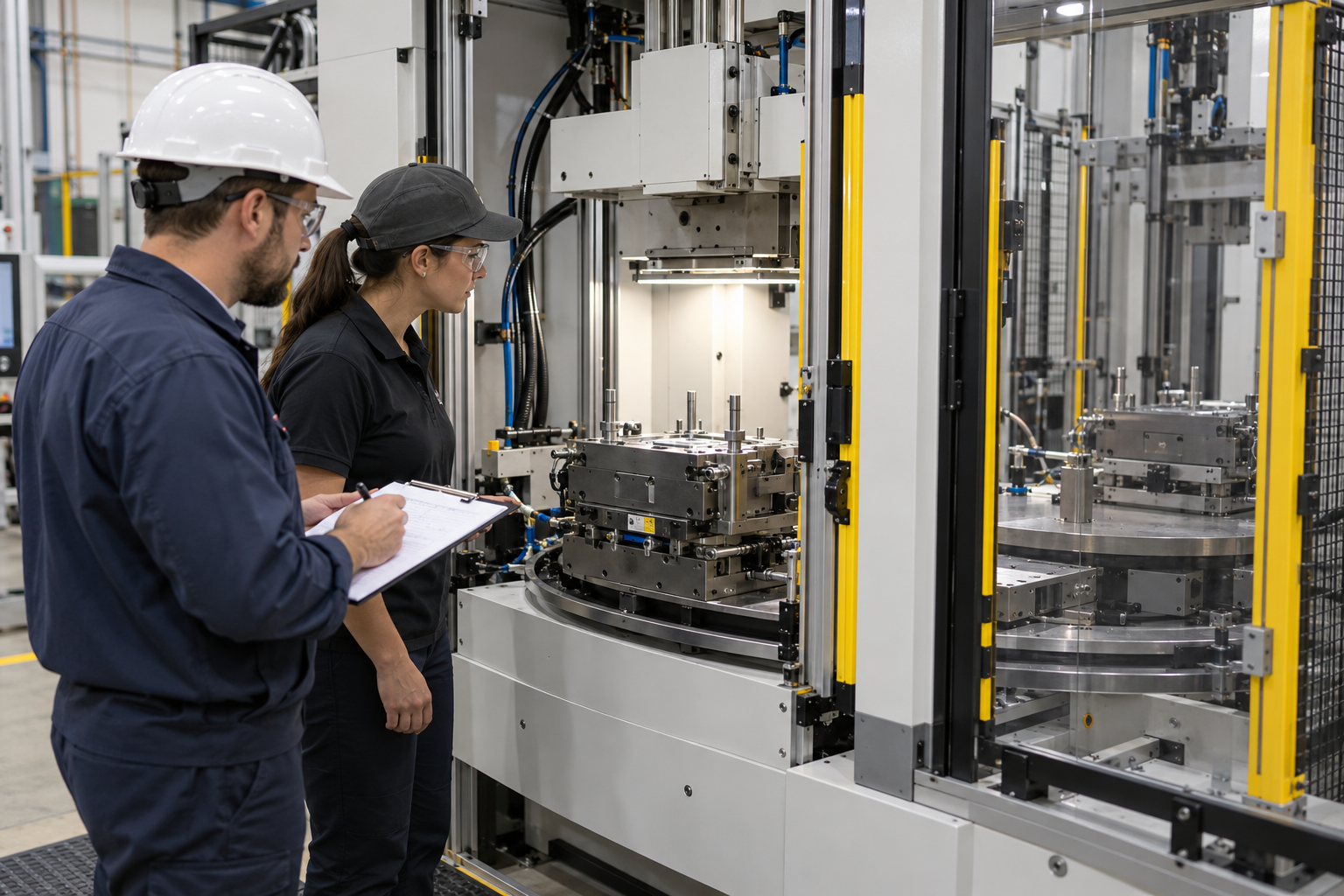
Insert confirmation deserves special attention because a missing, reversed, or partially seated insert can damage tooling or produce hidden defects. The cell may use mechanical nests, presence sensors, vision, or a validated manual confirmation depending on the risk. The selected method must work at every applicable station and remain accessible for verification. Sensor logic should distinguish a genuine ready condition from a bypass or stale signal. Buyers should document how the machine prevents indexing or molding when the required condition is absent.
Part removal can be more demanding than loading when cured silicone grips the core or when delicate geometry can deform. The project should define whether removal is manual, ejector-assisted, air-assisted, robot-assisted, or fully automated. It should also specify where the part is supported immediately after release. A dedicated unloading position may be valuable only when it improves access or protects the next loading task. Trials should use production-intent mold surfaces and part geometry because demonstration samples can understate real removal effort.
Safety architecture and guarded access
Rotary movement, vertical clamping, ejection, injection, and robot motion create separate hazards that must be addressed as one safety system. The risk assessment should identify each access point, operating mode, stored-energy source, and foreseeable intervention. Guard doors, interlocks, light curtains, enabling devices, emergency stops, and safe motion functions must match the configured cell and applicable requirements. Safety devices should not be positioned where normal material handling causes nuisance trips. A nuisance-prone system encourages unsafe workarounds and unreliable output.
The machine should have defined modes for automatic production, setup, mold change, maintenance, and fault recovery. Each mode needs clear authority over table movement, clamp movement, ejection, robot access, and auxiliary devices. A stopped table is not automatically safe if pneumatic, hydraulic, thermal, gravitational, or electrical energy remains. Lockout points and dissipation steps should be documented and reachable. Training should include abnormal conditions, not only the normal automatic cycle.
Emergency-stop coverage should be assessed from every normal operating and intervention position. The team should verify that activation produces the expected safe response across the machine, dosing system, robot, and peripherals. Restart must require a deliberate sequence and must not create unexpected table or clamp motion. Bypasses, overrides, and maintenance permissions should be controlled and recorded. The final acceptance record should identify the tested device, location, response, result, and responsible reviewer.
Tooling strategy and mold ownership
The cost comparison must include all lower molds, upper mold components, heated bases, transfer fixtures, nests, sensors, and spare interface parts required by each architecture. A layout with more stations may need duplicate tooling or station-specific hardware before it can deliver its intended sequence. The product record for the Vertical 3RT LSR Injection Molding Machine mentions a fixed heated mold base and configurable ejection, but the exact tooling concept must be confirmed for the proposed part. Buyers should request a tooling matrix that states what is common, duplicated, movable, or dedicated. That matrix also clarifies changeover scope.
Mold mass and center of gravity affect table loading, indexing behavior, bearing life, and safe handling. The buyer should provide verified weights for every installed assembly, including fixtures, inserts, manifolds, and connection hardware. The supplier should return allowable values and the proposed load distribution for the exact table. Tooling should be checked in every rotational position, not only at the clamp. Any future mold family should remain within the validated envelope rather than being assumed compatible.
Thermal behavior can differ between a mold under the heated clamp and a lower mold waiting at an accessible station. The process plan should identify which components remain heated, which are exposed, and how temperature stability is monitored. Insert temperature, waiting time, and station dwell can affect filling and cure even when the injection recipe is unchanged. A multi-station layout should therefore be tested after warm-up and during representative interruptions. Acceptance should include recovery after a planned stop, not only steady-state production.
Automation and peripheral interfaces
Robot integration should start with a task definition and a shared coordinate concept. State whether the robot loads inserts, unloads parts, performs inspection, applies release treatment, transfers trays, or combines several tasks. Define the robot-safe position required before indexing and the machine-safe condition required before robot entry. Exchange signals should include ready, permission, cycle state, fault, reset, and part-quality status as needed. The interface list should be reviewed jointly by the machine and automation teams.
A rotary-table cell needs physical clearance for grippers, hoses, cameras, lighting, conveyors, and rejected-part handling. Clearance must be checked through the full robot path and every machine position, including maintenance positions. The layout should provide a route for material and finished parts without crossing guarded hazards or blocking operator access. Cable carriers and utility connections should not rub, twist, or enter the tooling envelope. A digital reach study is useful, but a physical dry cycle remains necessary.
The dosing system, mold temperature controls, vacuum equipment, and downstream inspection devices also affect architecture selection. Their alarms should be visible to the machine control or coordinated through a documented stop strategy. A table should not index into a new cycle when a required peripheral is unavailable or when material condition is uncertain. Recipe management must identify which machine, mold, dosing, and automation settings belong together. Change control should prevent an operator from combining incompatible recipes.
Control logic and traceability
Station identity must remain unambiguous after indexing, stopping, manual movement, and power restoration. The control should know which tooling or part state occupies each position and should challenge any uncertain condition before resuming automatic operation. If station identity relies on sensors or encoded positions, those devices need diagnostic coverage and an acceptance test. The HMI should communicate actionable states without exposing unsupported shortcuts. Recovery instructions should be written for the actual sequence and available at the machine.
Traceability requirements vary by part and customer, so the RFQ should state the required level rather than assume a universal solution. Possible records include recipe version, material batch, mold identification, station identity, cycle result, alarm history, inspection result, and operator authorization. The architecture may influence how easily these records are associated with a specific part. A three-position process can create more intermediate states that the controls must track. Data fields should be verified for meaning, retention, export, and time synchronization during acceptance.
Alarm design should distinguish a machine fault from a part-quality hold or a missing upstream condition. Operators need a safe, repeatable recovery path that preserves station identity and prevents mixed parts. Maintenance staff need enough diagnostic detail to locate failed sensors or interrupted handshakes. Alarm history should capture the originating condition rather than only the final stop. A fault-injection test can reveal whether the proposed controls support real production better than a flawless demonstration does.
Maintenance, cleaning, and changeover
More stations can increase the number of mold faces, locating elements, connectors, sensors, and protected spaces that require cleaning or inspection. The machine layout should let technicians reach these items without unsafe body position or removal of unrelated assemblies. Lubrication points, filters, table-drive components, ejectors, and safety devices need clear service intervals. Hot mold areas should be identifiable and shielded where necessary. The maintenance review should use the supplied access drawings and a walk-through on the completed cell.
Mold change time should include cooldown or hot-work controls, utility disconnection, lifting, table positioning, cleaning, installation, alignment, connection, recipe selection, safety checks, warm-up, and first-piece approval. A multi-station machine may require handling several lower tools and verifying each station separately. Quick connections can reduce time only when they remain reliable, labeled, and protected from incorrect mating. Lifting points and devices should be defined before shipment. A witnessed changeover is often more informative than a headline changeover estimate.
Spare-parts planning should cover architecture-specific items as well as common machine components. Table sensors, reference switches, drive components, rotary connections, station fixtures, and special ejector parts may deserve dedicated spares. The supplier should identify long-lead items and provide exact part references for the delivered configuration. The buyer should also confirm software backup, parameter backup, and restoration procedures. A machine that cannot be restored confidently after component replacement carries hidden downtime risk.
RFQ data that supports a valid comparison
A useful RFQ begins with 3D part data, material information, annual demand, cavity target, insert details, quality criteria, and production environment. It should also include available floor space, utility limits, operator assumptions, automation scope, downstream handling, and required records. The buyer should state whether the project prioritizes flexibility, labor separation, compact footprint, future automation, or the lowest validated unit cost. Conflicting priorities should be ranked. Without this input, suppliers may quote different production concepts under similar machine names.
Ask each supplier to return a station sequence, cycle-time breakdown, responsibility matrix, layout, safety concept, tooling concept, interface list, utility schedule, and acceptance plan. The response should identify assumptions and exclusions in plain language. Requested options should be priced separately so the team can see which feature creates which benefit. Product family names should be tied to configuration codes and revision-controlled drawings. This turns the comparison into an engineering decision instead of a marketing comparison.
Commercial evaluation should separate base machine cost from project cost and operating exposure. Include molds, duplicate lower tooling, robots, guarding, feeders, vision, conveyors, installation, training, validation, spares, and expected changeover work. Avoid assigning an ROI percentage until cycle time, staffing, yield, maintenance, and utilization have been verified for the real part family. Run several scenarios instead of one favorable forecast. A simpler rotary cell can be the stronger investment when it meets takt with less complexity.
Factory acceptance testing
Factory acceptance should begin with document review and configuration identity. Confirm the machine model, installed options, table or station arrangement, mold interfaces, dosing connection, guarding, software version, and supplied manuals against the purchase specification. Record serial or configuration references without relying on informal photographs. Verify that drawings reflect the built cell. Close documentation discrepancies before performance testing so results remain traceable.
Dry-cycle tests should challenge indexing, station recognition, interlocks, ejection, robot handshakes, alarms, and recovery without risking production tooling. Repeat the sequence enough times to expose intermittent behavior and test at representative speed. Interrupt the cycle at different positions, restore utilities, and confirm that the control does not lose station state. Check that manual commands are limited by mode and safety conditions. Record failed tests, corrective action, and witnessed retest.
Process trials should use production-intent material, inserts, mold, handling, and inspection criteria whenever practical. Measure accepted cycle time, handling balance, part quality, temperature stability, station consistency, and operator workload. Sample parts from each station identity so a station-specific issue cannot hide inside an average. Include startup, steady production, a planned pause, and restart. The run duration should be agreed in the purchase specification and should be long enough to represent the main risks.
| Acceptance stage | Checks | Record | Release condition |
|---|---|---|---|
| Configuration | Model, stations, options, drawings, interfaces | Signed configuration list | Built cell matches approved revision |
| Dry cycle | Indexing, identity, interlocks, recovery | Cycle and fault log | No unresolved unsafe or ambiguous state |
| Process run | Material, mold, inserts, takt, quality, workload | Station-linked sample results | Agreed criteria met with production-intent inputs |
| Site handover | Utilities, peripherals, recipes, training, backups | SAT and training records | Open items closed before production release |
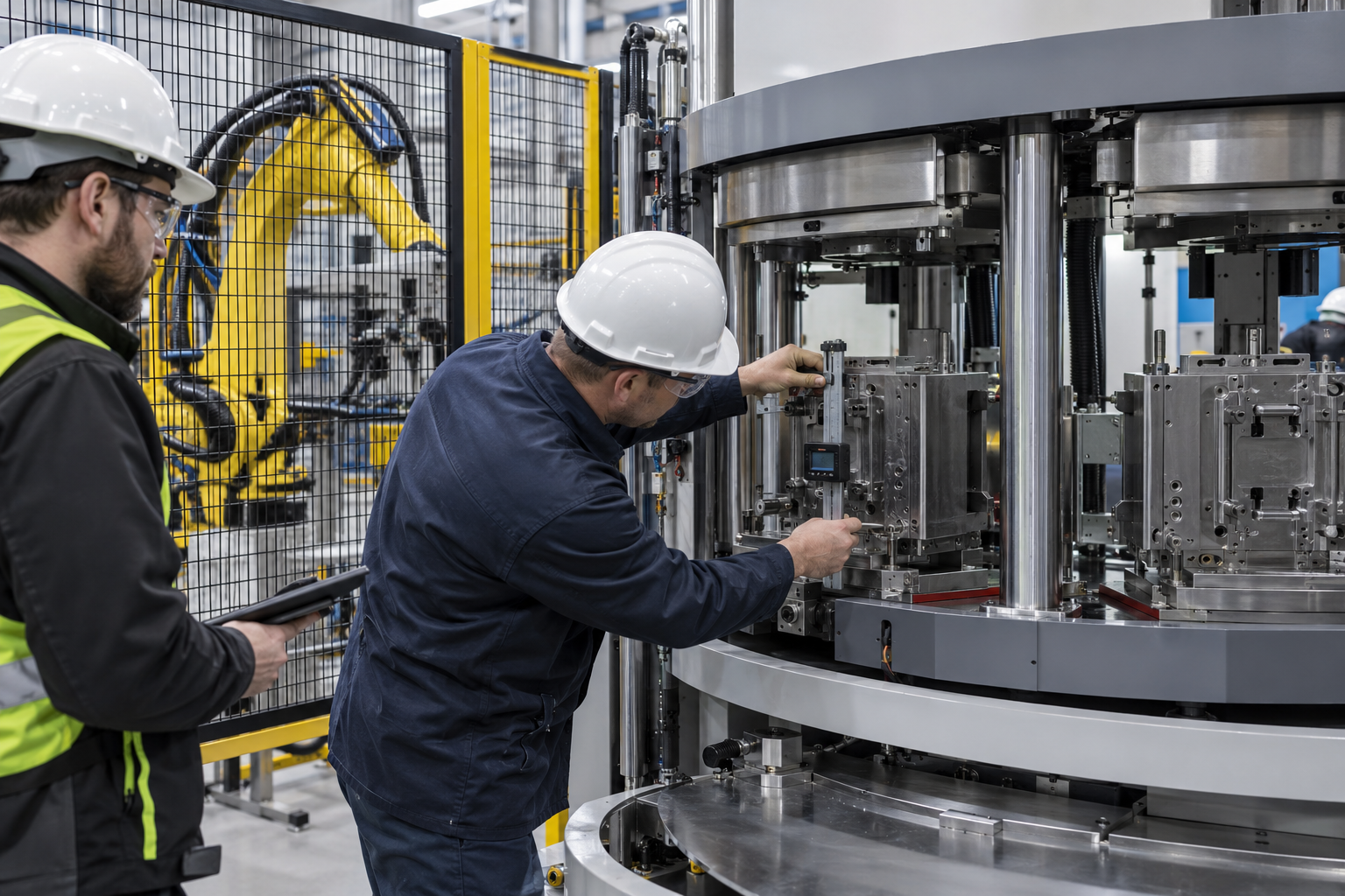
The comparison should include repeatable position arrival and tooling clearance, but it should not duplicate a separate detailed study of rotary indexing accuracy. For A4, the acceptance focus is whether the configured architecture supports safe transfer, reliable clamping, correct station identity, and the required process sequence. Any numeric positioning tolerance must come from the approved machine and tooling documents. Measure with an agreed method and calibrated equipment. Treat an unsupported generic tolerance as a risk rather than a promise.
Site acceptance and production handover
Site acceptance repeats critical functions after transport, installation, utility connection, and line integration. Confirm leveling, anchoring if applicable, electrical and pneumatic connections, dosing interfaces, guarding, exhaust or ventilation needs, and safe access. Run each machine mode and every connected peripheral. Verify that transferred recipes and backups match the factory-approved version. Document deviations caused by the site environment and close them before production release.
Operator training should cover loading, insert checks, normal start, normal stop, quality holds, alarm response, safe recovery, cleaning, and communication with maintenance. Maintenance training should cover energy isolation, table reference, sensor diagnostics, lubrication, backup, restoration, and architecture-specific wear points. Training needs hands-on exercises rather than a presentation alone. Competence should be confirmed on the delivered configuration. Updated work instructions should remain at the site after handover.
A controlled production ramp is safer than immediate full-rate scheduling. Start with defined inspection frequency and trace station-related defects until the process demonstrates stability. Review minor stops, recovery time, operator balance, mold condition, and peripheral alarms each shift. Adjust standardized work only through an approved change process. The final release should link machine acceptance, mold approval, process capability, safety closure, and trained personnel.
Choose by evidence, not station count
Choose the vertical rotary-table concept when its accessible work station, dual-lower-mold logic, footprint, and integration plan meet the verified part route with appropriate simplicity. Evaluate the Vertical 3RT concept when a third position supports a defined loading, unloading, inspection, cooling, or automation task that cannot be balanced effectively in the simpler sequence. Neither architecture is automatically faster, safer, or more flexible. The best choice is the least complex configured cell that satisfies takt, quality, access, traceability, and future plans. The purchase specification and witnessed tests should make that conclusion auditable.
Relevant configured machine families
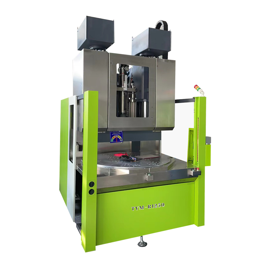
Vertical Turntable LSR Injection Molding Machine
A vertical rotary-table product family for projects using accessible loading and guarded molding positions.
View Product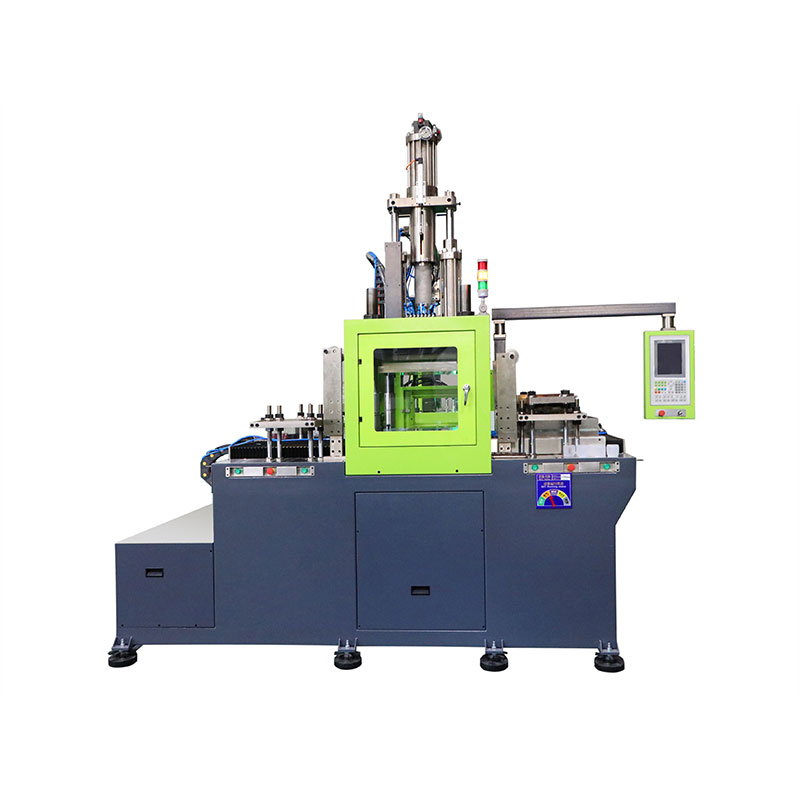
Vertical 3RT LSR Injection Molding Machine
A configurable 3RT machine family that must be matched to the project-specific station sequence and tooling plan.
View Product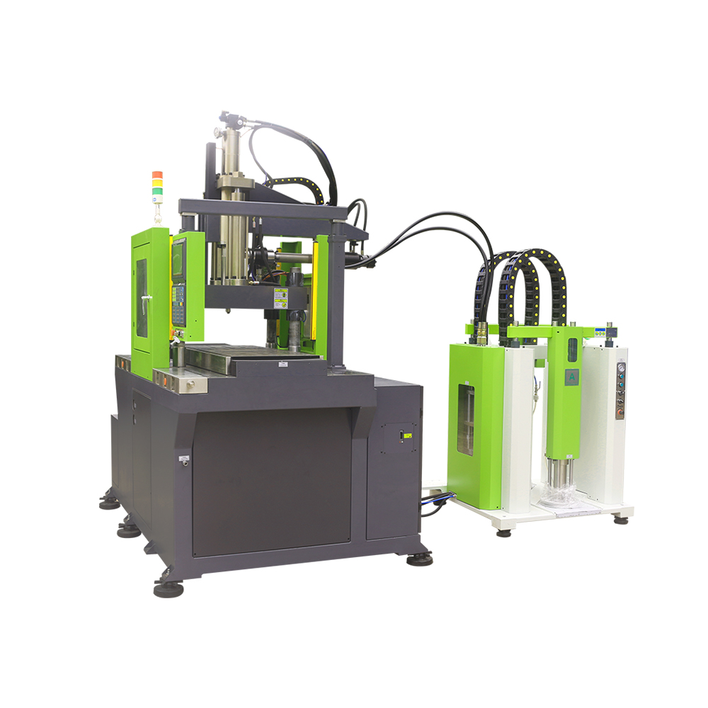
Vertical LSR Injection Molding Machine
A vertical machine family for insert overmolding cells requiring project-specific mold and handling integration.
View Product

You May Also Like
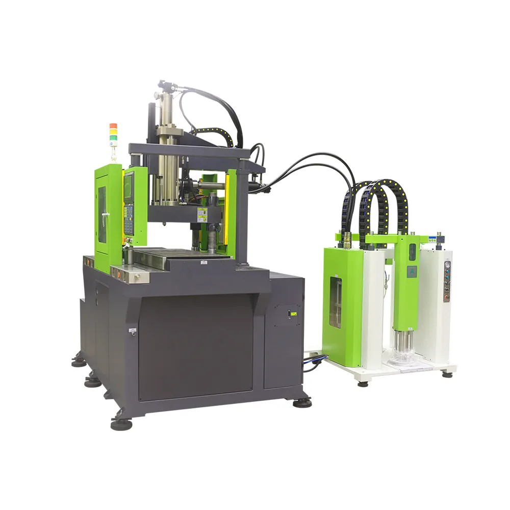
The vertical machine will open and close the mold in the vertical direction. The double slide plate can be installed with one upper mold and two lower molds. It can cooperate with the double station operation to improve the production efficiency, and is more suitable for the production of rubber coated products of silica gel package inserts.
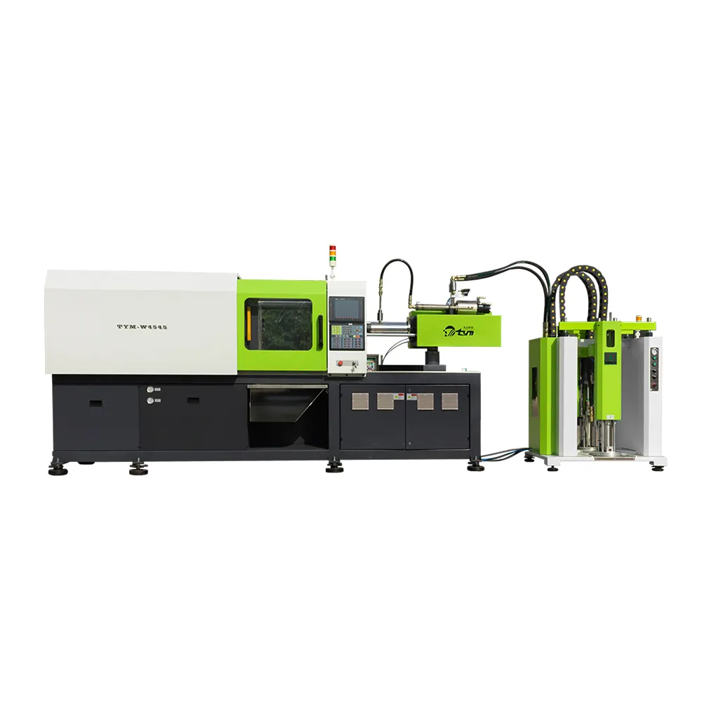
Direct pressure mold opening and closing system.It's more suitable for producing the LSR parts which can be automatically removed from the mold.It can be used for the production of silicone products in multiple industries - automotive wiring harnesses, baby pacifiers, menstrual cups, medical valve plugs.
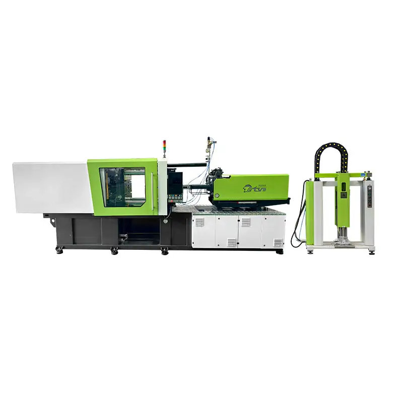
Direct pressure mold opening and closing system.It's more suitable for producing the LSR parts which can be automatically removed from the mold.
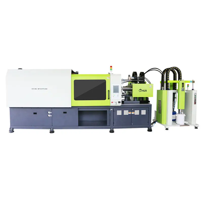
There are two injection units, two separate feed systems and color slurry addition systems. A unified system control panel can be used to achieve two different colors or hardness of liquid silicone. Formed in the machine at the same time, Suitable for the production of double color silicone products or double hardness silicone products.
Inquire About Our Latest Updates
Saw an interesting update or new technology in our news section? Leave us a message below for more detailed information, technical data, or event follow-ups.
Have a project in mind? Talk to our LSR experts and get a tailored turnkey solution.
Email: sales01@gdtym.com
WhatsApp/Phone: +86 18814115468
© 2026 TYM. All Rights Reserved.

Facebook
TikTok
TYM Silicone Machinery